Build with us!

INSTRUCTIONS
TOOLS
Included in kit:
- HEX 1.5mm screwdriver
Also needed:
- soldering iron: use a small to tip
- solder
- solder wick
- flux
- wire snips
- pliers
SOLDERING
Most of the Parts you will be soldering are trough hole parts, meaning they have many legs / pins.
You will solder most of these parts from the bottom side of the PCB. This side also holds the tiny SMD components. Pay special attention to stay away from them. Choose the direction you solder from wisely. Almost all the solder joints have space on one side for the tip of your soldering iron.
Many of the parts you will solder have more than one pin (leg). Solder one leg at first to hold it, then push the component in place while heating with the other hand. Once it is seated, solder other legs. This may sound tedious, in fact its a lot more tedious to fix a crooked part, so ensure perfect seating from the beginning.
Use flux. Solder wire contains flux, which makes the solder flow much better. With time, the flux evaporates. If you feel, the solder doesn’t really get liquid anymore, do yourself a favor and add some flux. Or clear solder joint using solder wick and resolder with fresh solder.
Aim for both the parts leg and the solder joint at once. Liquid solder likes hot surfaces.
Heat or cool: Decide, move in with the iron and get maximum heat to the component or release and don’t touch the solder joint. Heat hard, cool hard. Don’t just touch a little.
When soldering through hole parts like switches, leds or potentiometers you will find yourself short of one hand: One hand for the iron, one holding the part in place and nobody there to put the solder in the right place. To get out of this misery find a friend or use the snake tamer technique. Form the solder wire into the shape of a dancing snake to make it sustain itself. Like this the solder can sustain itself. Try increase the windings lying on the work surface to stabilize the solder wire.
MODULES ASSEMBLY
Every module is built from the same layers:
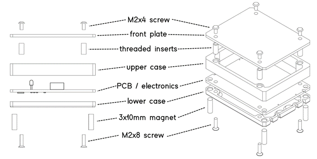
There are different classes of module cases, named after width and variation. Assemble all modules in the following 3 steps:
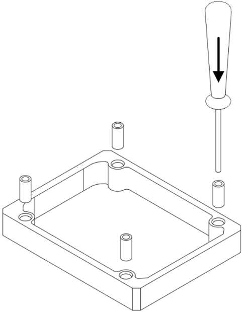
Step 1 – prepare top case
Take upper case and lay on side with more holes. press in the threaded inserts using the HEX1.5 screwdriver. Mount front plate using M2x4 screws.
Press in 3x10mm magnets from bottom side: Use base to ensure orientation, press in a bit by hand, press entire module against surface to fully seat magnets.
Step 2 – solder the PCB
Take the pcb, one side has the small SMD components, that is the bottom side. On the top side of the board you will install SMD and / or THT components depending on the module. Start with the SMD components:
SMD micro trimmers, minijack sockets, electrolytic caps
Next solder the through hole parts, that will be hidden behind the front plate: film caps, transistors, LDR
At last mount all the components that will interface the front plate: potentiometers, LEDs, patch points, screw trimmers. Before soldering mount the top case assembly to ensure placement and solder one leg of each part to check alignment before soldering all the pins. Maybe use some flux and or high soldering temperature to conquer the patch points at last. Be extra careful to get proper alignment by using a patch cable to secure patch points in place before soldering.
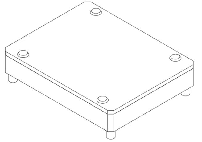
Step 3 – final assembly
Combine pcb and top case and finish the module using M2x8 countersunk screws
Step 4 – calibration
tweak here
Some modules have buttons or small trimmers
- digital modules (adcs / dacs)
- v/oct VCO / VCF calib.